Topic 4 - SLAM
Introduction:
SLAM (Simultaneous Localization and Mapping) is the computational problem of constructing or updating a map of an unknown environment while simultaneously keeping track of an agent’s location within it.
IMPORTANT: Before proceeding further, start to download the docker image. Another download link (download the folder).
ORB-SLAM3
ORB-SLAM3 is the first real-time SLAM library able to perform Visual, Visual-Inertial and Multi-Map SLAM with monocular, stereo and RGB-D cameras, using pin-hole and fisheye lens models. It is based on detecting the ORB features on an image, matching the features by the descriptors and final optimization. It is a third version of an ORB-SLAM system. A very brief changelog of versions:
- 2015, ORB-SLAM - monocular version
- 2017, ORB-SLAM2 - monocular, stereo vision, RGB-D versions
- 2020, ORB-SLAM3 - monocular, stereo vision, RGB-D versions, with or without IMU measurements. Combining multiple maps for a full world map building.
ORB-SLAM3 system consist of three threads:
- tracking thread - responsible for determining the change in position from frame to frame.
- mapping thread - responsible for improving localization accuracy by optimizing the connected poses and points in the map.
- loop closure thread - responsible for detecting the return to a known location and correcting drift.
The threads work asynchronously, which leads to obtaining slightly different results upon different runs.
Steps of ORB SLAM3 processes:
Tracking:
- Detection and description of ORB features in the image.
- Matching features from the current and previous frame based on descriptors.
- Calculation of transformation.
Mapping:
- Verification if the frame is a key one (needed for improving the system accuracy).
- Finding additional matches to the recently seen features from the map.
- Transformation correction.
Stereo vision
We will test the stereo vision version of the ORB-SLAM3 system.
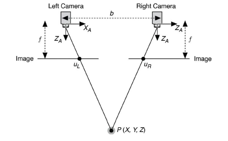
Stereo vision is a technique used to perceive depth. It works by capturing two images of the same scene from slightly different viewpoints using two cameras. The process involves:
- Identifying corresponding points: Features present in both images are matched.
- Calculating disparity: The difference in position (horizontal shift) of these corresponding points between the two images is measured.
- Determining depth: The disparity is inversely proportional to the distance from the cameras—larger disparities indicate closer objects, while smaller disparities indicate farther ones.
- By analyzing this disparity across the images, a depth map can be computed, enabling 3D visualization of the scene.

Running ORB-SLAM3 on the data custom stereo vision data:
The ORB-SLAM3 system will be tested on the data recorded from the car which circled the Piotrowo campus. The whole route was about 1.3 km long. The data sequence consists of images from two cameras(~20 Hz), DGPS data (~10 Hz). DGPS data provided localization information with an accuracy of about several centimeters, which is enough for our purpose to evaluate the localization accuracy of the system.
Environment preparation
- Allow the container to display GUI applications (on a host machine):
xhost +local:root- Load the downloaded docker image with ORB-SLAM3 setup. You can also use the Dockerfile to build the image yourself but it will likely take more time.
docker load < path/to/file.tar.gz2a. If you build the docker image from Dockerfile, download and run the docker image building script:
wget https://raw.githubusercontent.com/kamilmlodzikowski/LabARM/main/Lab07-ORB-SLAM/arm_07_build.sh
bash arm_07_build.sh- Download the script for running the docker container: arm_07_run_gpu_nvidia.sh if you use nvidia GPU or arm_07_run_cpu.sh script otherwise. Run the container:
wget <script_link>
bash <script_name>.shNOTE: You can attach a new terminal to the container using the following command:
docker exec -it ARM_07 bash
- Set ROS_DOMAIN_ID environment variable (replace
<CHOSEN_NUMBER>with a random number between 0-101 or 215-232):
grep -q ^'export ROS_DOMAIN_ID=' ~/.bashrc || echo 'export ROS_DOMAIN_ID=<CHOSEN_NUMBER>' >> ~/.bashrc
source ~/.bashrc
Stereo vision camera calibration
To run the stereo vision version of the ORB-SLAM3 on our data, we
have to provide the parameters of the used camera configuration. The
initially prepared configuration file PP.yaml can be found
in the /arm_ws/src/orbslam3_ros2/config/stereo directory.
Current values are correct for a different camera configuration, so the
task is to correct the values. You have to modify the following
parameters:
Camera.fx- focal lengthCamera.fy- focal lengthCamera.cx- principal point coordinateCamera.cy- principal point coordinateCamera.width- width of the camera image in pixels (set it to 720)Camera.height- height of the camera image in pixels (set it to 540)Camera.bf- horizontal focal length multiplied by the baseline of stereo vision system. It refers to the absolute value located in the upper right corner of the P2 matrix in the output ofstereoRectifyscript mentioned below. The baseline of the stereo vision system is the distance between cameras.LEFT.height- height of the left camera image in pixels (set it to 540)LEFT.width- width of the left camera image in pixels (set it to 720)LEFT.D- distortion coefficients of left cameraLEFT.K- camera intrinsic matrix of left cameraLEFT.R- rectification transform (rotation matrix) for the left cameraLEFT.P- projection matrix in the rectified coordinate systems for the left cameraRIGHT.height- height of the right camera image in pixels (set it to 540)RIGHT.width- width of the right camera image in pixels (set it to 720)RIGHT.D- distortion coefficients of right cameraRIGHT.K- camera intrinsic matrix of right cameraRIGHT.R- rectification transform (rotation matrix) for the right cameraRIGHT.P- projection matrix in the rectified coordinate systems for the right camera
To obtain all of the necessary stereo vision system parameters, it has to be calibrated. In this example, it was already done with the use of kalibr toolbox. Here is the description of how it was done.
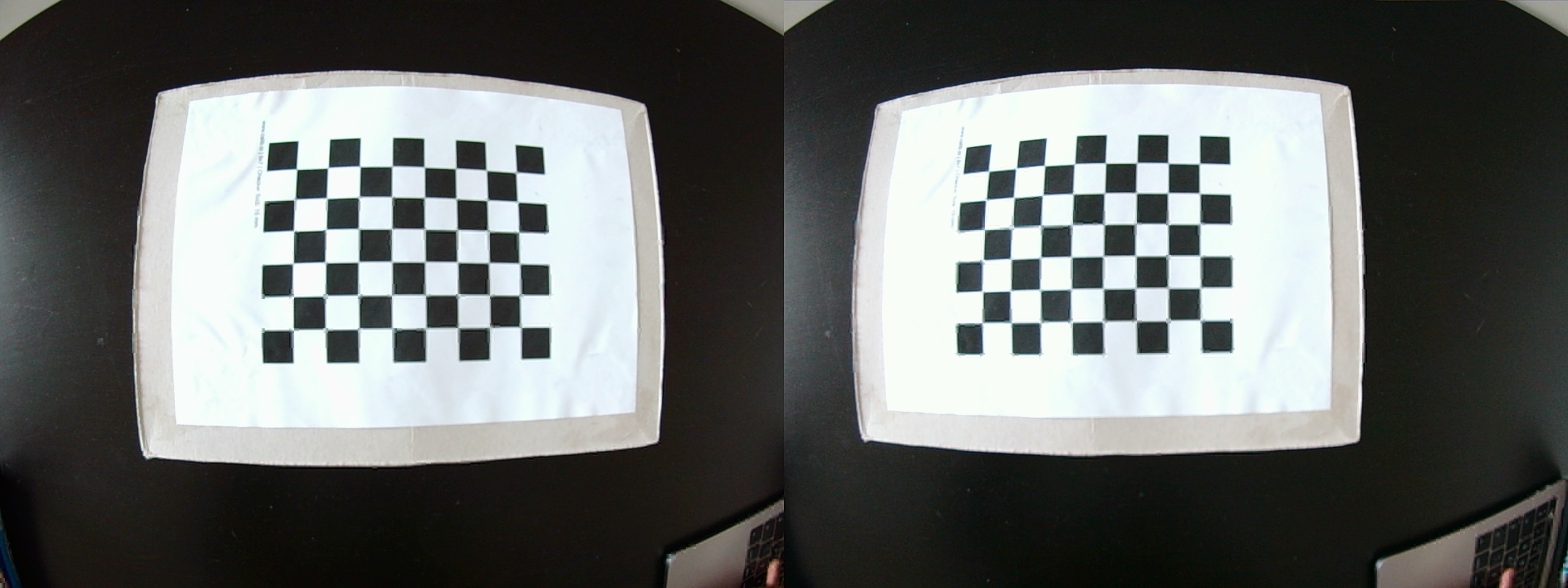
In short, a stereo vision system is calibrated by capturing multiple synchronized image pairs of a known calibration pattern, such as a checkerboard, using both cameras. The calibration pattern has to be visible in the field of view of both cameras. Feature points (e.g., corners) are detected in each image, and their correspondences across the two views are identified. Such set of images is used ot estimate the intrinsic parameters of both cameras (focal length, principal point, distortion coefficients) and extrinsic parameters of a stereo vision system (rotation and translation between cameras) using an optimization process.

The output of the calibration process from kalibr was
the following:
cam0:
  cam_overlaps: [1]
  camera_model: pinhole
  distortion_coeffs: [-0.23248459123344795, 0.08191912671589296, 7.839314739418238e-05, 4.2075874672940684e-05]
  distortion_model: radtan
  intrinsics: [589.7363083173951, 590.0729541236071, 369.91183932674056, 298.34374442536097]
  resolution: [720, 540]
  rostopic: /pylon_stereo_node/left/image_raw
cam1:
  T_cn_cnm1:
  - [0.9997283077554007, 0.02320592542857902, 0.0021899081072863703, -0.32185797263546406]
  - [-0.0232254786906617, 0.9996863295720175, 0.00937121157638949, 0.0074867236444067856]
  - [-0.001971753560855992, -0.00941952715496201, 0.9999536912757833, -0.002949869596374046]
  - [0.0, 0.0, 0.0, 1.0]
  cam_overlaps: [0]
  camera_model: pinhole
  distortion_coeffs: [-0.2303444874136257, 0.07876654742388302, 9.186197190170094e-05,
    -0.0005160611286370294]
  distortion_model: radtan
  intrinsics: [589.5069022640636, 589.958834706832, 379.29038618376575, 283.91319737264314]
  resolution: [720, 540]
  rostopic: /pylon_stereo_node/right/image_raw
HINT: The explanation of the output above can be found here and here.
kalibrnotation of camera intrinsics [fu fv pu pv] is equivalent to [fx fy cx cy].
Some of the parameters can be taken directly from the
kalibr calibration output (Camera.fx,
Camera.fy, Camera.cx, Camera.cy,
LEFT.height, LEFT.width, LEFT.D,
LEFT.K, RIGHT.height,
RIGHT.width, RIGHT.D,
RIGHT.K).
To obtain the bf value, R, and
P matrices, we have to use stereoRectify
function from OpenCV, which calculates the transformations
(R, P) necessary to get and use the canonical
camera configuration (re-project image planes onto a common plane
parallel to the line between optical centers of images) for depth
estimation.
You can use the prepared script template
/arm_ws/src/orbslam3_ros2/scripts/stereoCalibration.py.
Firstly, fill the values in the script, based on the above
kalibr calibration output:
K1andK2- camera intrinsics matrices,d1andd2- distortion coefficients vectorsR- rotation matrixT- translation vector.
You should also adjust the image size in
stereoRectify()function call from (0, 0) to (720, 540).
To get the output of stereoRectify() run:
python /arm_ws/src/orbslam3_ros2/scripts/stereoCalibration.pyUseful knowledge:
Camera intrinsic matrix:

Homogeneous
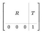
transformation matrix (T_cn_cnm1 is in this form):

Run ORB-SLAM3:
- Run ORB-SLAM3 ROS node along with the visualization:
ros2 run orbslam3 stereo /arm_ws/src/orbslam3_ros2/vocabulary/ORBvoc.txt /arm_ws/src/orbslam3_ros2/config/stereo/PP.yaml true- Replay the bag file:
ros2 bag play -r 0.25 bags/put_car -p --remap /pylon_stereo_node/left/image_raw:=/camera/left /pylon_stereo_node/right/image_raw:=/camera/right- After the replay of all data, shut down the ORB-SLAM3 node with
ctrl + cin the terminal where the node is running. The output trajectory will be saved.
Trajectory evaluation:
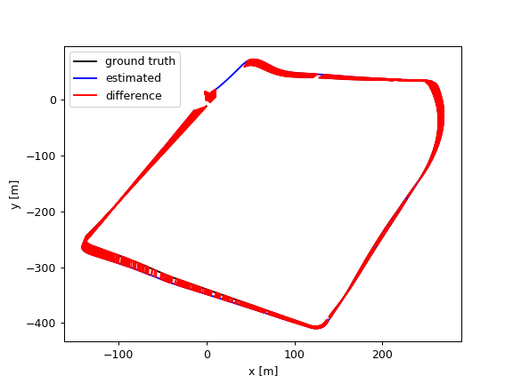
To evaluate the output trajectory we will compare it with the DGPS data as a ground truth. DGPS data was already processed to the correct format (TUM trajectory format with poses in UTM coordinate system).
- Download the DGPS ground truth data:
wget https://chmura.student.put.poznan.pl/s/7axxzw5EXqaM2Oy/download -O dgps.txt- Run the evaluation using the prepared script:
python3 /arm_ws/src/orbslam3_ros2/scripts/evaluate_ate.py <DGPS_DATA_PATH> <ORBSLAM_OUTPUT_PATH> --verbose --plot trajs.pngExample output:
compared_pose_pairs 1460 pairs
absolute_translational_error.rmse 21.493264 m
absolute_translational_error.mean 20.317460 m
absolute_translational_error.median 22.098146 m
absolute_translational_error.std 7.011507 m
absolute_translational_error.min 9.798730 m
absolute_translational_error.max 35.219433 m
The script computes the best overlap of the two given trajectories and calculates the absolute translational error. The system is not deterministic so the results can vary a little between runs. The output trajectories can be displayed with:
apt update
apt install viewnior
viewnior trajs.png
